CROCODILE TECHNOLOGY TO Make REAL PCB
 | Once a circuit has been designed and simulated / tested in Crocodile Technology and any necessary alterations made, the completed circuit is ready for export to ‘real PCB’®. Both Crocodile Technology and Real PCB software must be running at the same time for this to be possible. (Please note: the uptodated version of Crocodile Technology is called Yenka Electronics. This allows the design and conversion of circuits to PCB, in an integrated environment) Circuit Wizard is a very good alternative piece of software that allows the design of circuits and conversion to PCB. The conversion to PCB layout can be achieved through a menu in Crocodile Technology. Real PCB converts the circuit diagram effortlessly to PCB layout and usually with 100% accuracy. Real PCB can also be used to construct a circuit as a PCB layout, from scratch, by selecting components from a series of menus and drawing the tracks connecting them. It can be used by both beginners and experts to produce accurate PCBs. Quality checks can be carried out automatically and the software will also produce a bill for the components used on any PCB. The ‘Pour Copper’ menu changes the final PCB by only removing enough copper so that the tracks can be seen. This means that only the necessary copper is removed to ensure the final circuit works. This extends the life of etchant used in the etchant tank. |
| | |
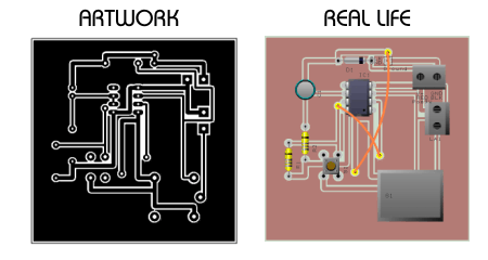
| Two more ways of presenting the PCB are shown below. The 'artwork' layout is the most likely to be printed out on a transparency, ready for conversion to PCB. The real life layout style shows the PCB with its components. This is useful when arranging the components on the PCB, as the position of each can be check against a real life printed. | |
When the PCB layout is finished it is printed on a transparency and becomes known as a PCB mask. The PCB mask is transferred to the UV box, which is the next stage in the manufacture of a printed circuit board. | |
 | |
Advantages of using circuit and PCB software: 1. Circuits can be simulated on screen without the need to build a circuit on a breadboard with real components. 2. Errors can be corrected and alterations made to the circuit by simply replacing components from menus. 3. No soldering is needed, simply move components with a mouse. 4. Using simulation software is safer than soldering with hot soldering irons and avoids dangerous fumes being produced whilst soldering. 5. Once a PCB has been designed it can be printed onto transparencies repeatedly, all to the same high quality. 6. PCB layout software is more accurate than drawing a circuit by hand. | |
Do you have any query or doubts,want to know that PLEASE ask it or leave your ideas at comment..or Just mail me:
MAil Me Your Query or Comments::
Friends,If you find anything incorrect here,PLEASE just inform me,to rectifies it !!!!!!!
0 comments:
Post a Comment