Mauris euismod rhoncus tortor

Mauris euismod rhoncus tortor

At vero eos et accusamus et iusto odio dignissimos ducimus qui blanditiis praesentium voluptatum deleniti atque corrupti quos dolores et quas molestias excepturi sint occaecati cupiditate non...

Sed nunc augue

Sed nunc augue

At vero eos et accusamus et iusto odio dignissimos ducimus qui blanditiis praesentium voluptatum deleniti atque corrupti quos dolores et quas molestias excepturi sint occaecati cupiditate non...

Why is it needed

Why is it needed

At vero eos et accusamus et iusto odio dignissimos ducimus qui blanditiis praesentium voluptatum deleniti atque corrupti quos dolores et quas molestias excepturi sint occaecati cupiditate non...

Where can I get some

Where can I get some

At vero eos et accusamus et iusto odio dignissimos ducimus qui blanditiis praesentium voluptatum deleniti atque corrupti quos dolores et quas molestias excepturi sint occaecati cupiditate non...

What is Lorem Ipsum?

What is Lorem Ipsum?

At vero eos et accusamus et iusto odio dignissimos ducimus qui blanditiis praesentium voluptatum deleniti atque corrupti quos dolores et quas molestias excepturi sint occaecati cupiditate non...

  • Mauris euismod rhoncus tortor
  • Sed nunc augue
  • Why is it needed
  • Where can I get some
  • What is Lorem Ipsum?
Showing posts with label Electronics. Show all posts

Tuesday, March 16, 2010

Making of PCB Final stage

0 comments
MANUFACTURE OF PCBS - FINAL STAGES
M.Manivasagam

When removed from the etching solution, the PCB is washed and a PCB eraser is used to remove any film from the tracks. This must be done carefully because the film will prevent good soldering of the components to the PCB. The tracks can be checked using a magnifying glass. If there are gaps in the tracks, sometimes they can be repaired using wire but usually a new PCB has to be etched.
 
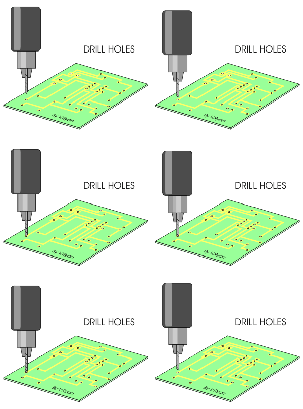
The last stage is drilling the holes for the components. A small PCB drill is used for this purpose.

Again care is needed as a good PCB can be ruined by careless drilling.
 

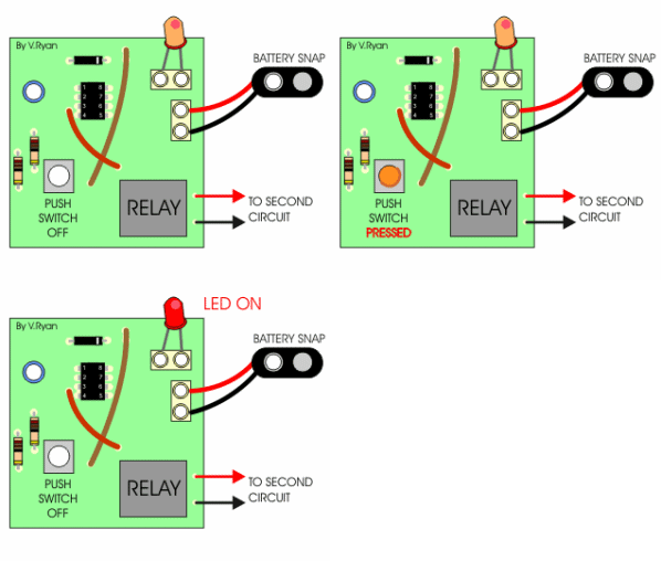
This completed Printed Circuit Board (PCB) has all its components soldered in position. It has been manufactured through the processes described in the information sheets.
PCBs manufactured in industry are designed on a computer and then manufactured on an production line controlled by computers. Usually there is very little human contact.
 
   
QUESTIONS:
1. Describe the stages involved in the manufacture of PCBs - using simple, labelled diagrams.
2. What safety precautions should you take when using ‘developer’ and the ‘etching solution’ ?
3. Complete the notes on the PCB sequence drawing OR place in order the cards representing each stage of manufacturing a PCB. Then place the correct text box underneath each picture.
4. List the advantages of using electronics / PCB simulation software compared to using a breadboard to test a circuit design.
5. What quality checks should be carried out when manufacturing a printed circuit board (PCB).
6. What material is a PCB?


Do you have any query or doubts,want to know that PLEASE ask it or leave your ideas at comment..or Just mail me:

MAil Me Your Query or Comments::

Friends,If you find anything incorrect here,PLEASE just inform me,to rectifies it !!!!!!!
Read More

Making of PCB boards-3

0 comments
MANUFACTURE OF PRINTED CIRCUIT BOARDS
M.Manivasagam


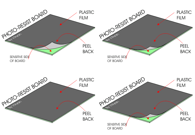
PHOTO-RESIST BOARD is a piece of glass reinforce plastic. One of the sides is copper clad and this copper has a photosensitive coating. When the plastic film is peeled back this sensitive coating is revealed.
After processing this will be the PCB.
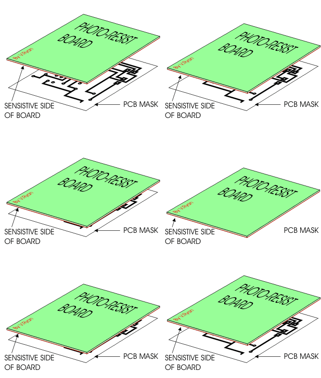
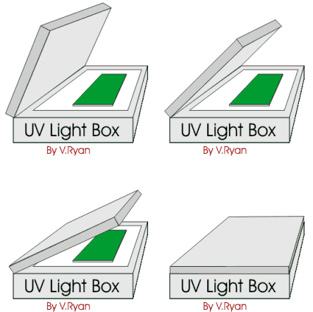
The PCB mask (now on a transparency) is placed underneath the photo-resist board, touching the sensitive surface. Remember the plastic film must be removed. PCB mask and board are then transferred to the UV light Box.

You must be careful to ensure that the PCB mask is the right way up, otherwise when the circuit is etched you will discover that the tracks are also the wrong way round.

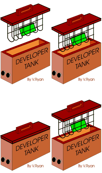
The lid is shut and the box switched on. The photo-resist board, with PCB mask are left underneath the lid for 2 ½ minutes. The photo-resist board is then placed in a tank filled with developer (using plastic tongs)
It is important that the board is only left in the developer for approximately ten seconds.

When the board is taken out of the developer it must be washed in clean water before transferring to the etching tank. Always use plastic tongs.

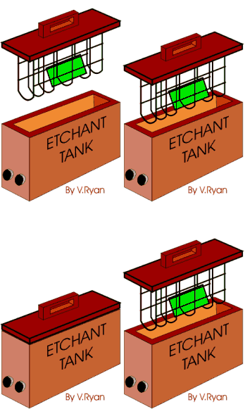
The etchant is held in a ‘bubble etch tank’ and is heated. This solution slowly etches away the unwanted copper, leaving the tracks only. At this stage it is important to keep checking that the PCB is completed (time - 15 to 45 minutes). If it is left in the tank too long the copper tracks will also be removed or damaged.


                               Click Here For Next Page(Final Stage)

Do you have any query or doubts,want to know that PLEASE ask it or leave your ideas at comment..or Just mail me:

MAil Me Your Query or Comments::

Friends,If you find anything incorrect here,PLEASE just inform me,to rectifies it !!!!!!!
Read More

Know How PCB boards are made

0 comments
Printed Circuit Boards - Introduction

Friends do you know how PCB boards are made,and what it had in this??Just go through this post.

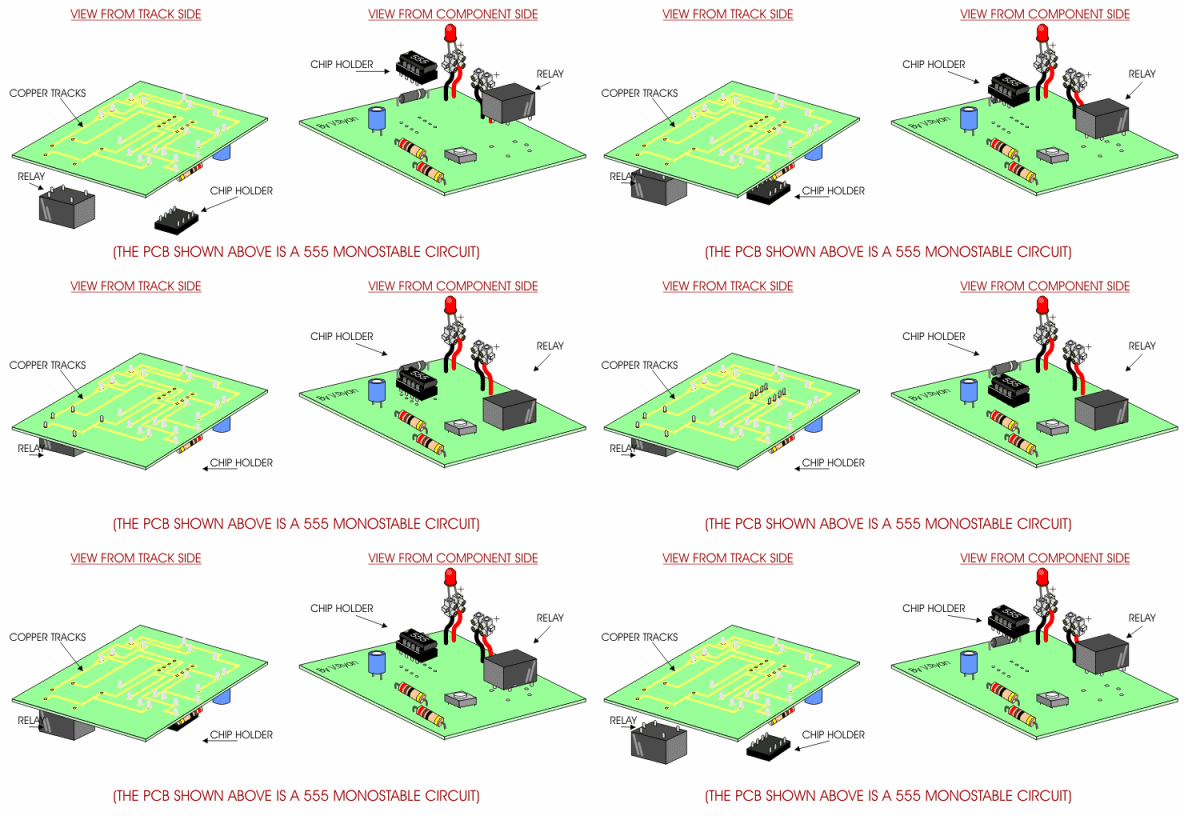
Electronic circuits in schools and industry are normally manufactured through the use of PCBs (Printed Circuit Boards). The boards are made from glass reinforced plastic with copper tracks in the place of wires. Components are fixed in position by drilling holes through the board, locating the components and then soldering them in place. The copper tracks link the components together forming a circuit. The animation shows the components arranged on the 'component side' of the PCB and as it rotates, the copper tracks are also shown.


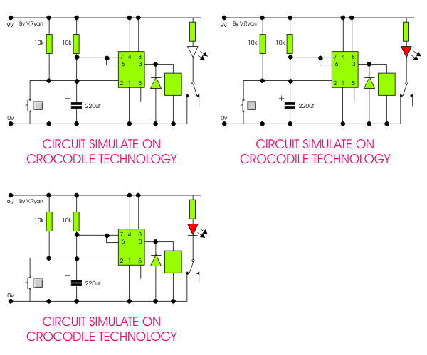
The two diagrams below show the track side of a PCB (normally the underneath side) and the component side (normally the top side) of the same circuit. The relay and integrated circuit are ready to be placed in position and soldered.


A circuit such as the one shown opposite can be drawn using software such as ‘Crocodile Technology®’ (now known as Yenka Electronics). This allows individual components such as resistors, integrated circuits and capacitors to be dragged onto the screen and connected together, forming a complete circuit. The finished circuit can then be simulated on screen. If the circuit is not correct it can be altered until it works in the desired way.
This allows you to test the circuit on the computer and correct any mistakes or make improvements. This saves time as there is no need to build the circuit with real components.
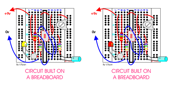
Circuits can also be built on a breadboard using real components. This is a time consuming method and often mistakes occur as many components are small and it is easy to connect components incorrectly, causing a circuit to fail. Also, breadboards are prone to damage as the small connections on the boards are quite delicate.
Using simulation software such as Crocodile Technology® is recommended as it is a much more reliable and accurate method of testing a circuit.


Do you have any query or doubts,want to know that PLEASE ask it or leave your ideas at comment..or Just mail me:

MAil Me Your Query or Comments::

Friends,If you find anything incorrect here,PLEASE just inform me,to rectifies it !!!!!!!
Read More

How to make Temperature Sensor

0 comments
A TYPICAL TEMPERATURE SENSOR
V. Ryan © 2005

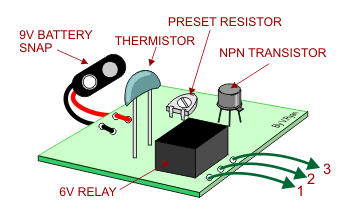
Opposite is a simple temperature sensor. It operates in exactly the same way as a light/dark sensor except that it has a component called a thermistor rather than a LDR (Light Dependent Resistor). The thermistor's resistance value changes when the temperature rises or falls. This ‘triggers’ the relay.The preset resistor allows the person using the circuit to alter its sensitivity to changes in temperature..
When are temperature sensors used?


Do you have any query or doubts,want to know that PLEASE ask it or leave your ideas at comment..or Just mail me:

MAil Me Your Query or Comments::

Friends,If you find anything incorrect here,PLEASE just inform me,to rectifies it !!!!!!!
Read More

Make a light,dark sensor by yourself

0 comments
 MAKING A LIGHT / DARK SENSOR


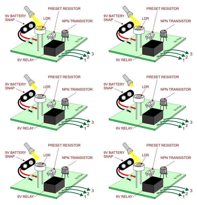
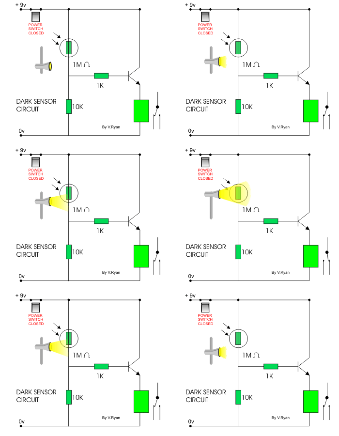
Opposite is a simple light/ dark sensor. This can be connected as an input or switch to another circuit. The sensors has three green wires (1, 2 and 3). Wire 2 should always be connected to one of the inputs. If wire 1 is also connected then the sensor acts as a dark sensor. If wires 2 and 3 are connected to the inputs then sensor operates as a light sensor.The preset resistor allows the person using the circuit to alter its sensitivity to light/dark.


CONSTRUCTING A CIRCUIT USING SIMULATION SOFTWARE
   
All circuits are drawn on software such as Crocodile Clips. Using this software the individual components can be joined together on the screen. Once the circuit is drawn its operation can be simulated to see if it works. If it fails it can be corrected on the computer screen and tested again.
Using software to test circuit designs saves time as there is no need to physically solder together components. It also saves money as components and materials are not wasted on failed circuits
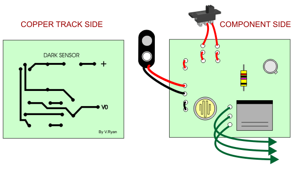
The circuit is then made into a PCB (Printed Circuit Board). Components are added and soldered in position (See PCB Section of this website). Two views of the same circuit are shown below. How do they differ?


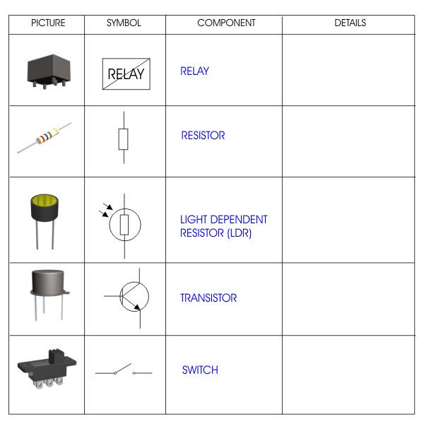
3. Complete the table below by writing some details about the components used in the light/dark sensor circuit.


Do you have any query or doubts,want to know that PLEASE ask it or leave your ideas at comment..or Just mail me:

MAil Me Your Query or Comments::

Friends,If you find anything incorrect here,PLEASE just inform me,to rectifies it !!!!!!!
Read More

Electronics Components and its woking in gif


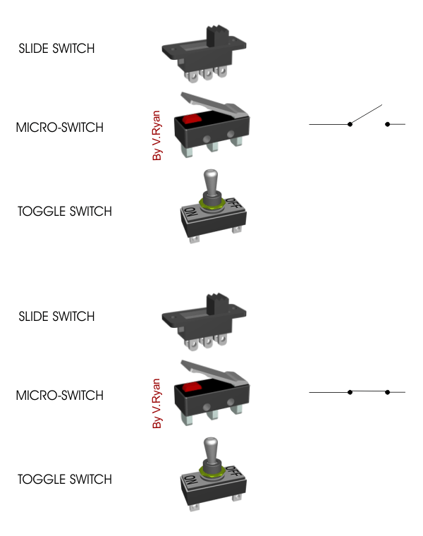
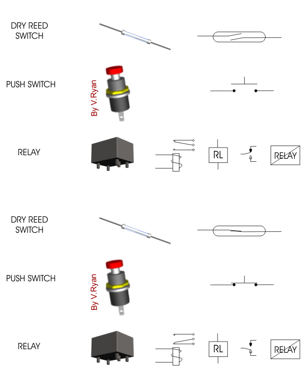
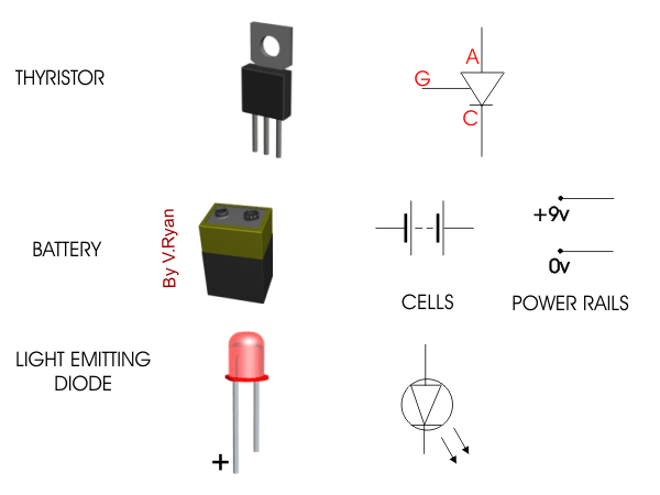
There are a large number of symbols which represent an equally large range of electronic components. It is important that you can recognise the more common components and understand what they actually do. A number of these components are drawn below and it is interesting to note that often there is more than one symbol representing the same type of component. (Check all your information sheets in the electronics section for more symbols).உங்கள் கேள்விகளை கேட்க மரகாதிர் .உங்கள் நண்பன் மணி 


Do you have any query or doubts,want to know that PLEASE ask it or leave your ideas at comment..or Just mail me:

MAil Me Your Query or Comments::

Friends,If you find anything incorrect here,PLEASE just inform me,to rectifies it !!!!!!!
Read More

Thursday, March 11, 2010

Know about Full Wave Rectifier

0 comments
Full-Wave Rectifier

The full-wave rectifier is essentially two half-wave rectifiers, and can be made with two diodes and an earthed center tap on the transformer. The positive voltage half of the cycle flows through one diode, and the negative half flows through the other. The center tap allows the circuit to be completed because current can not flow through the other diode. The result is still a pulsating direct current but with just over half the input peak voltage, and double the frequency.

A full-wave rectifier converts the whole of the input waveform to one of constant polarity (positive or negative) at its output. Full-wave rectification converts both polarities of the input waveform to DC (direct current), and is more efficient. However, in a circuit with a non-center tapped transformer, four diodes are required instead of the one needed for half-wave rectification.Four diodes arranged this way are called a diode bridge or bridge rectifier:


For single-phase AC, if the transformer is center-tapped, then two diodes back-to-back (i.e. anodes-to-anode or cathode-to-cathode) can form a full-wave rectifier. Twice as many windings are required on the transformer secondary to obtain the same output voltage compared to the bridge rectifier above.

Full-wave rectifier using a transformer and 2 diodes.

Full-wave rectifier, with vacuum tube having two anodes.

A very common vacuum tube rectifier configuration contained one cathode and twin anodes inside a single envelope; in this way, the two diodes required only one vacuum tube. The 5U4 and 5Y3 were popular examples of this configuration.

A three-phase bridge rectifier.

3-phase AC input, half & full wave rectified DC output waveforms

For three-phase AC, six diodes are used. Typically there are three pairs of diodes, each pair, though, is not the same kind of double diode that would be used for a full wave single-phase rectifier. Instead the pairs are in series (anode to cathode). Typically, commercially available double diodes have four terminals so the user can configure them as single-phase split supply use, for half a bridge, or for three-phase use.

Disassembled automobile alternator, showing the six diodes that comprise a full-wave three-phase bridge rectifier.

Most devices that generate alternating current (such devices are called alternators) generate three-phase AC. For example, an automobile alternator has six diodes inside it to function as a full-wave rectifier for battery charging applications.

The average and root-mean-square output voltages of an ideal single phase full wave rectifier can be calculated as:


Where:
          Vdc,Vav - the average or DC output voltage,
          Vp - the peak value of half wave,
          Vrms - the root-mean-square value of output voltage.
           π = ~ 3.14159
           e = ~ 2.71828

 Peak loss:

             An aspect of most rectification is a loss from the peak input voltage to the peak output voltage, caused by the built-in voltage drop across the diodes (around 0.7 V for ordinary silicon p-n-junction diodes and 0.3 V for Schottky diodes). Half-wave rectification and full-wave rectification using two separate secondaries will have a peak voltage loss of one diode drop. Bridge rectification will have a loss of two diode drops. This may represent significant power loss in very low voltage supplies. In addition, the diodes will not conduct below this voltage, so the circuit is only passing current through for a portion of each half-cycle, causing short segments of zero voltage to appear between each "hump".

Do you have any query or doubts,want to know that PLEASE ask it or leave your ideas at comment..or Just mail me:

MAil Me::
Read More

Wednesday, March 10, 2010

How to Add RAM to Your Pc

0 comments
 These instructions are intended to be used in conjunction with your model-specific owner manual.
Note: The memory module contain electronic components that are sensitive to electrostatic discharge (ESD). Improper handling could damage your computer. Leave the module in its protective anti-static bag until ready to install, and handle it only as instructed by your Computer Manufacturer. If you have reservations about installing the module, ask for assistance from a qualified technician.
INSTALLATION PROCEDURE
1. Place the computer power switch in the "off " position and disconnect the AC power cord.
2. Remove the computer top cover following the instructions in the model-specific owner manual.
3. Before touching any electronic components, make sure you first touch an unpainted, grounded metal object to discharge any static electricity stored on your clothing or body.
 4. Locate the memory expansion sockets on the computer motherboard. If all the sockets are full, remove smaller capacity modules to allow room for higher capacity modules.
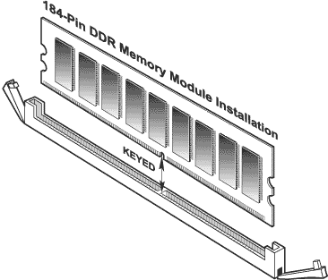
5. The ejector tabs shown in the illustration are used to remove a module. By pushing outward on the ejector tabs, the module will pop-up from the socket and it can then be removed.
6. Handle your new module carefully; do not flex or bend the module. Always grasp the module by its edges.
7. For most installations, DDR modules can be installed in any available expansion slot. Other installations may require the memory to be installed in a particular sequence based on the modules capacity. Check your owner manual to determine the correct installation sequence for your configuration.
  • Insert the module into an available expansion socket. Note how the module is keyed to the socket. This ensures the module can be plugged into the socket one way only. Firmly press the module into position, making certain the module is completely seated in the socket. The ejector tabs at each end of the socket will automatically snap into the locked position. Repeat this procedure for any additional modules you are installing.

  • install_ddr
    8. Once the module or modules have been installed, the computer top cover can be reinstalled.
    9. Plug in the AC power cord and reinstall any cables disconnected during the installation process.
    10. Turn on the computer and follow the instructions in your computer owner manual that describe the steps necessary to allow your computer to recognize the newly installed memory.


    Do you have any query or doubts,want to know that PLEASE ask it or leave your ideas at comment..or Just mail me:

    MAil Me::
    Read More

    Construction of Transistor

    0 comments

    Transistor Construction:

    A transistor is constructed by placing a oppositely doped semiconductor material between two similarly doped semiconductors. Or placing n-type material between two p-type material which forms the pnp-transistor or by placing a p-type material between two n-type semiconductor which forms npn-transistor.
    PNP Transistor Construction.svg
    The above diagram shows the schematic construction of a PNP transistor. As you can see an N-type silicon (green layer) is sandwiched between two P type materials (red layer). The left part is indicated by P+ which means its highly doped P-type material. This highly doped portion is called Emitter, that is the piece of semiconductor that supplies majority carriers for the transistor to function. At the extreme right is moderately doped P type material which is called as the Collector. This portion collects the majority charge carriers that is been emitted by Emitter and that manage to cross the collector. The middle region is denoted by n- because it's doped with N-type impurities. The minus'-' sign indicates it's doped very very less compared to the emitter and collector. The middle region is called the Base, and it's this region that serves as a gate, regulating flow of charge from Emitter to collector.
    The doping of base is just one tenth of that of collector. In a real transistor, the width of base is very thin. The total width of the transistor will be 150 times that of the width of the base.
    In a similar way by sandwiching a lightly doped P region between highly and moderately doped N region we get a NPN transistor as shown below.
    NPN Transistor Construction.svg

     Transistor Operation

    To see how transistor perates we will look at how an PNP transistor works. NPN transistor works the same way as PNP, but with voltage and currents reversed.
    Below is the diagram of PNP transistor. One can see that its emitter is held more positive than base and base more positive than collector. When emitter-base is forward biased and collector based is reversed bias, the transistor is said to be in active region. It's in the active region that transistor acts as a amplifer and so on. So let's study about it.
    See the image below for active biasing of PNP transistor.
    Now let's sat we remove the voltage between base and collector hence the circuit looks as follows.
    Let's analyze it.

    Common Base Configuration:

    It has following properties:
    • low input impedance
    • high output impedance
    • high voltage gain
    • unity (or less) current gain

    Common Emitter Configuration:

    As well as being used as a switch to turn load currents "ON" or "OFF" by controlling the Base signal to the transistor, NPN Transistors can also be used to produce a circuit which will also amplify any small AC signal applied to its Base terminal.

    If a suitable DC "biasing" voltage is firstly applied to the transistors Base terminal thus allowing it to always operate within its linear active region, an inverting amplifier circuit called a Common Emitter Amplifier is produced. One such Common Emitter Amplifier configuration is called a Class A Amplifier. A Class A Amplifier operation is one where the transistors Base terminal is biased in such a way that the transistor is always operating halfway between its cut-off and saturation points, thereby allowing the transistor amplifier to accurately reproduce the positive and negative halves of the AC input signal superimposed upon the DC Biasing voltage. Without this "Bias Voltage" only the positive half of the input waveform would be amplified. This type of amplifier has many applications but is commonly used in audio circuits such as pre-amplifier and power amplifier stages.
    With reference to the common emitter configuration shown below, a family of curves known commonly as the Output Characteristics Curves, relates the output collector current, (Ic) to the collector voltage, (Vce) when different values of base current, (Ib) are applied to the transistor for transistors with the same β value. A DC "Load Line" can also be drawn onto the output characteristics curves to show all the possible operating points when different values of base current are applied. It is necessary to set the initial value of Vce correctly to allow the output voltage to vary both up and down when amplifying AC input signals and this is called setting the operating point or Quiescent Point


    Do you have any query or doubts,want to know that PLEASE ask it or leave your ideas at comment..or Just mail me:

    MAil Me::
    Read More

    What is Operational amplifier

    0 comments

    Operational amplifier


    **An operational amplifier, which is often called an op-amp, is a DC-coupled high-gain electronic voltage amplifier with a differential input and, usually, a single-ended output.  An op-amp produces an output voltage that is typically millions of times larger than the voltage difference between its input terminals.

     **Typically the op-amp's very large gain is controlled by negative feedback, which largely determines the magnitude of its output ("closed-loop") voltage gain in amplifier applications, or the transfer function required (in analog computers). Without negative feedback, and perhaps with positive feedback for regeneration, an op-amp essentially acts as a comparator. High input impedance at the input terminals (ideally infinite) and low output impedance at the output terminal(s) (ideally zero) are important typical characteristics.

    **Op-amps are among the most widely used electronic devices today, being used in a vast array of consumer, industrial, and scientific devices. Many standard IC op-amps cost only a few cents in moderate production volume; however some integrated or hybrid operational amplifiers with special performance specifications may cost over $100 US in small quantities.

    ** Op-amps sometimes come in the form of macroscopic components, (see photo) or as integrated circuit cells; patterns that can be reprinted several times on one chip as part of a more complex device.
    The op-amp is one type of differential amplifier. Other types of differential amplifier include the fully differential amplifier (similar to the op-amp, but with two outputs), the instrumentation amplifier (usually built from three op-amps), the isolation amplifier (similar to the instrumentation amplifier, but which works fine with common-mode voltages that would destroy an ordinary op-amp), and negative feedback amplifier (usually built from one or more op-amps and a resistive feedback network).
    Read More

    Bipolar Junction Transistor

    0 comments

    Bipolar junction transistor


    A bipolar (junction) transistor (BJT) is a three-terminal electronic device constructed of doped semiconductor material and may be used in amplifying or switching applications. Bipolar  transistors are so named because their operation involves both electrons and holes.

    Charge flow in a BJT is due to bidirectional diffusion of charge carriers across a junction between two regions of different charge concentrations. This mode of operation is contrasted with unipolar transistors, such as field-effect transistors, in which only one carrier type is involved in charge flow due to drift.

    By design, most of the BJT collector current is due to the flow of charges injected from a high-concentration emitter into the base where they are minority carriers that diffuse toward the collector, and so BJTs are classified as minority-carrier devices.

    Read More

    Know the Computer to Connecting Tv problems

    0 comments

    Computer to TV Troubleshooting


    HDCP Problems:

    **The majority of high-definition DVDs and downloadable content is copy protected with a technology called HDCP (High-bandwidth Digital Content Protocol). This means that every piece of equipment you use to play HD content must be HDCP-enabled -- everything from the computer to the cable to the HDTV. If you can't play HD content through your computer, than your graphics card might not be HDCP compliant.

    **The biggest problem with connecting your computer to your TV is that, generally speaking, computers and TVs don't display at the same resolutions. For example, the closest thing to the HDTV resolution 720p (1280 x 720) is a monitor display mode called XGA (1280 x 960). Not quite the same. And the closest thing to 1080p (1920 x 1080) is a monitor display mode called WUXGA (1920 x 1200). Again, not quite the same.

    The result, in most cases, is something called overscan, where the full computer screen image doesn't fit on the TV screen. Overscan is a bigger problem on SDTVs where the native screen resolution is much smaller than your computer's display. If you're going to use an SDTV as a monitor, plan on lowering your screen resolution to 800 x 600.


    **HDTVs also have overscan problems, but usually only the very edge of the computer image gets cropped. A bigger problem with HDTVs is when the TV refuses to display a signal that doesn't fit its native resolution.

    Luckily, most HDTVs have the ability to scale incoming signals to match their native screen resolution. This involves either upconverting lower-resolution signals in the attempt to bring the resolution up to high definition or downconverting higher-resolution signals for lower-resolution screens. It's not perfect, but for most casual viewers, there's little to no noticeable loss in image quality.


    **In rare cases, the HDTV won't recognize the resolution of the signal sent by your computer. When you connect an external display to your computer, most graphics cards will automatically try to find a good match for the display's native resolution. If this doesn't work, you will probably need to edit your resolution with third-party software.


    Two programs are considered the best solutions for solving connectivity problems between a computer and a TV: PowerStrip for Windows and DisplayConfigX for Mac. Both of these programs allow you to match your graphics card's resolution precisely with the native resolution of your TV. If your HDTV is 1080p, you can go into one of these programs and switch your computer's resolution to 1920 x 1080, even if this wasn't previously an option.

    Avoid increasing the refresh rate on your graphics card, unless you have a 120-hertz HDTV. If you send a signal with a refresh rate over 60 hertz to a normal HDTV, you could damage the TV.

    For any other query you have please say it via comment,let us know and let all may learn....
    Read More

    Computer to Tv Connecting cables

    0 comments

    Computer TV Cables


    S-Video cables
    ©iStockphoto/FokinOl
    S-Video cables
    ­If you read our article "How do I know which cables to use?" then you know there is a baffling number of audio/video cables on the market. You'll have to make some sense of the different types of wiring necessary to connect your computer to your TV. First you need to figure out what kinds of audio/video outputs your computer has and what kinds of audio/video inputs your TV has. If you're lucky, you'll find a match right away. But depending on the type of equipment you own, you may need to get creative.

    First, let's talk about which cables you'd use to connect a computer to a standard-definition TV. The most common video inputs on an SDTV are composite, S-video and component video. On computers, the most common video output is S-video. On a desktop PC, you'll find the 9-pin S-video jack on your graphics card next to where you connect your monitor.

    Some Windows laptops also have S-video-out jacks, but most have 15-pin VGA jacks for connecting to external monitors. Luckily, it's easy to find adapters and special cables that have VGA connectors on one end and S-video connectors on the other. Apple also sells a wide variety of adapters to connect Mac desktops and laptops to the S-video or composite jack on SDTVs.

    Even if you have an old TV that only accepts coaxial video cable (the one-pin variety that's mostly used for cable TV and satellite connections), you can use something called an RF converter box that can convert S-video or VGA input into coaxial output.

    For connecting a computer to an HDTV, it's the same story. The most common HDTV inputs are component video, DVI and HDMI. If your graphics card doesn't have one of these outputs, then you'll need to buy a special converter box or adapter. For example, if your computer only has a VGA jack and your HDTV only accepts HDMI, then you'll need to buy a small box that will convert the signal for you.

    Wireless Connections
    Apple TV is a small device that lets you connect your computer (Mac or PC) to your widescreen TV wirelessly. While you can use it to watch movies and TV shows through iTunes and browsing photo libraries, you can't use it as a regular computer.
    If you're serious about playing high-definition content from your computer on your HDTV, then you should upgrade to a graphics card with a DVI or HDMI output. Most newer Apple laptops come with a Mini DisplayPort video output that easily connects with the DVI or HDMI inputs on an HDTV.

    All of the cables that we've mentioned so far are video-only cables, which means that you'll need separate cables to handle your audio. The easiest solution is to connect some computer speakers to your audio card's headphone or audio-out jack. If you want to use your TV's built-in speakers, then you'll need to buy a 1/8-inch stereo mini-plug-to-RCA cable.

    For the best possible audio, you'll need to invest in an audio card for your computer with either an optical or digital coaxial audio output. These connections carry high-bandwidth digital audio signals using cables that can be plugged directly into your home theater receiver.

    Even if you have the right cables and have done your homework about resolutions, you still might have some problems connecting your computer to your TV.

    In the next section, we'll share some troubleshooting tips.

    For any other query or request please say it via comment.It may be helpful to others!!!
    Read More

    How to Connect Your Computer to Your TV

    0 comments

    Bill Gates shows off Microsoft Windows XP Media Center Edition
    Jeff Christensen/WireImage/Getty Images
    In 2005, then-Microsoft Chairman and CEO Bill Gates shows off the company's Windows XP Media Center Edition software, which can be used to deliver video, music and photos from a computer to a TV.
    ­

    How to Connect Your Computer to Your TV

    There's something painfully ironic about sitting on your living room couch, just a few feet away from a beautiful widescreen HDTV, watching a movie on your tiny laptop. Yet this is what most of us do when we download movies or TV shows onto our computers.

    The same goes for showing off our latest digital photos to friends. We all huddle around the 15-inch computer display while the TV screen goes unused. And what about that PowerPoint presentation you just gave at work? Wouldn't it have looked 1,000 times better on the wall-mounted plasma display in the conference room?

    There are many compelling reasons why we want to connect our computers to our televisions, especially now that HDTVs are so popular. Everything from movies to photos to work presentations were made for the big-screen experience.

    The first personal computers used TVs for monitors, but computer graphics technology quickly outpaced the image quality on standard-definition TVs (SDTVs). The typical modern computer monitor  has the ability to display images at a much higher resolution than a regular TV. A computer monitor can display more individual pixels than an SDTV.
    Even today, hooking a computer to an SDTV only makes sense if you want to use your computer as a DVD player. If you try to use an SDTV as a monitor, you'll have a hard time getting your full desktop to fit on the screen.

    But with the advent of high-resolution, high-definition TVs like flat-panel LCDs, plasma, LCoS, and DLP displays, televisions now make excellent computer monitors. In fact, that's what the manufacturers of PC-based media centers are trying to achieve. The tricky part is figuring out exactly which TVs work with which computers and how to connect them all together.

    Keep reading to learn more about bringing your small-screen life to the big leagues.


    Screen Resolution and Aspect Ratio

    Many people are familiar with the concept of screen resolution. Resolution is a measurement of how many individual pixels your TV or computer monitor can display at once. The old cathode ray TV (CRT) in your basement can display the equivalent of about 300,000 pixels [source: Kindig]. The latest HDTVs can display more than 2 million pixels. With more pixels, the image can be rendered in greater detail. It's the difference between painting a portrait with a thick sponge block or a small, delicate brush.

    The standard way to classify TV resolution is with numbers like 480i, 720p, 1080i and 1080p. The bigger the number, the greater the screen resolution. The little "i" and "p" stand for interlaced and progressive scan. This has to do with the way in which the image is rendered on the screen. Refresh rates on TVs and computer monitors are measured in hertz. A refresh rate of 60 times per second translates to 60 hertz. An interlaced-scan TV refreshes half of the screen image 60 times per second. It refreshes the odd-numbered horizontal lines first and then the even-numbered lines. The result is that the full screen refreshes 30 times a second.


    On a progressive scan television, the entire screen refreshes 60 times a second. The result is that progressive scan TVs have a noticeably smoother image when watching sports or other video with fast-moving action. All computer monitors are progressive scan [source: PCMag.com]. Some even have refresh rates faster than 60 times a second. This is why interlaced SDTVs make for lousy computer monitors. When you scroll, the image can't refresh fast enough to keep things smooth. As a result, you see that telltale flicker.

    Resolution is important, but you must also take a screen's aspect ratio into account. Your goal when hooking your TV up as a monitor is to make the entire image fit within the boundaries of the TV screen. SDTVs use a 4:3 aspect ratio -- the ratio of the screen's width to its height is 4 to 3. HDTVs have a native 16:9 aspect ratio. While many computer monitors share those aspect ratios, not all of them do, and your computer may support many different screen resolutions with different aspect ratios.

    In fact, your computer's preferences are unlikely to tell you the aspect ratio, and instead will tell you the resolution. The horizontal x vertical measurement is also the most common way to label computer monitor resolution. Some typical monitor resolutions are 640 x 480, 800 x 600 and 1024 x 768. If you don't know your monitor resolution, you can find out by going to whatismyscreenresolution.com. If you aren't connected to the Internet and you're using a Windows PC, right-click on the desktop and choose Preferences. Then choose the Settings tab. On a Mac, go to System Preferences and click Displays.


    The trick is to find the resolution that best fits the TV's aspect ratio. This may not be as big a deal as it sounds, though. Modern operating systems can usually match the attached monitor's aspect ratio automatically. If your computer doesn't, you can manually adjust the settings in your computer's preferences to make it fit.

    But there's more to hooking these two machines together than resolution and aspect ratio. You still have to get the information from the computer to the TV.
    In order to do that, we've got to solve the cable conundrum.

    For any quer's and your request just say it via comment.we are always to here from you!!!!!!!! 
    Read More

    Saturday, March 6, 2010

    Electronics the most basic-2

    0 comments
    **Electronics is that branch of science and technology which makes use of the controlled motion of electrons through different media and vacuum. The ability to control electron flow is usually applied to information handling or device control.

    **Electronics is distinct from electrical science and technology, which deals with the generation, distribution, control and application of electrical power. This distinction started around 1906 with the invention by Lee De Forest of the triode, which made electrical amplification possible with a non-mechanical device.

    **Until 1950 this field was called "radio technology" because its principal application was the design and theory of radio transmitters, receivers and vacuum tubes.

    **Most electronic devices today use semiconductor components to perform electron control. The study of semiconductor devices and related technology is considered a branch of physics, whereas the design and construction of electronic circuits to solve practical problems come under electronics engineering. This  focuses on engineering aspects of electronics.
    Read More